
Installation of the hardware
Note
During the installation process you must at all times take the provisions of the safety, maintenance and legal notices into account.
Model OM1
Hardware Installation
Wall-mounted
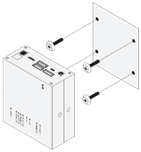
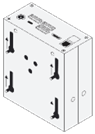
- Accurately measure the hole pattern for the mounting points.
Tip
The GM Energy Controller has a hole pattern of 80mm x 63mm (W x H).
The screw head should not exceed a diameter of 7mm (e.g., a universal screw of 4 x 40mm is recommended).
For a flush mount, ensure the screws protrude no more than 8mm from the wall.
- Insert the required screws into the surface where the GM Energy Controller will be mounted, ensuring they are securely fastened.
- Carefully align the GM Energy Controller with the installed screws and slide it into place. Ensure it is securely mounted.
DIN-rail mount
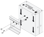
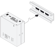
- Attach the DIN-rail mount to the GM Energy Controller using the provided screw holes.
- Carefully attach the GM Energy Controller to the DIN-rail. Ensure it is securely mounted.
Note
DIN-rail mounts need to be ordered seperately.
Electrical Installation
Power Supply
The GM Energy Controller requires a 12V (2A) DC power supply connected via a 5.5mm jack. The required power adapter is included in the delivery package.
Connecting the interfaces
See the supported device guides and the wiring & connectivity guidelines for the connection of devices.
Network Connection
The GM Energy Controller must always be connected to a wired (RJ45) network interface to ensure reliable communication and functionality. See also the wiring & connectivity guidelines.